The Apache helicopter is one the objects in the scene that will be animated as the blades will be spinning in order to show a flying helicopter. Firstly though, I must produce the apache helicopter along with all the extra parts, like the missiles and rockets that are on the wings.
The first thing I did was place the blueprints into 3DS max on 3 different planes, in order to model the helicopter. Luckily, the tutorial I used has blueprints of the helicopter readily available to download, however the same blueprints can be found on
www.the-blueprints.com. To set up the blueprints in 3DS max, I firstly constructed 3 planes, one for the side view, one for the top view and one for the front view. I then used the 3 images below and mapped them on to each plane.
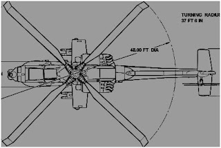

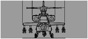
I then made sure each plane was the same size as each blueprint picture to make sure that I didn’t lose clarity with the pictures, as well as making sure that each edge of the blueprints matches up with the others. The sizes are as follows:
Top – 430 x 288
Side – 430 x 125
Front – 288 x 125
I then used the material editor to map the images on to the planes. I did this by adding a bitmap parameter to the diffuse colour map. After doing this, I then added the blueprints to each material as well as changing the ambient colour to white. This allowed me to fully see the blueprints properly in the scene:
After achieving this, I then started creating the helicopter. However, before I began creating the main body, I made a new material in the material editor, which would make the main body translucent. I did this so I could view the blueprints through the model, and make alterations without constantly changing the viewpoint. This was done by simply making the box white and changing the opacity to 50%.
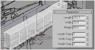
I then created the first box with the parameters shown above. This is because the helicopter’s body is made up of 7 different segments in total and the length, width and height match the black outlines on the blueprints. The next step was to create the basic outline of the main body by moving the vertices into the correct places along the blueprint.
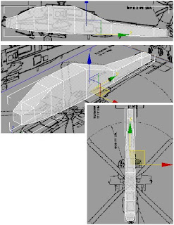
As you can see from the pictures, the seven segments, as each segment will model a different area to the helicopter. The first area I modelled was the cockpit.
I did this by selecting the edges on the side of the helicopter whilst back-facing was turned on in order to select the edges on the opposite side.
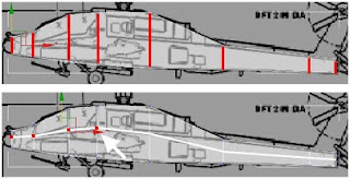
After doing this I then selected connect on the rollout section under edges on the right hand side. This cuts the apache in half and leaves a line across the entire model. I then moved the vertices upward in order for the edge to match up with the windows of the cockpit.
After doing that, I selected the 3 edges at the end of the cockpit, which were the top edge and the left and right edge around the top edge.
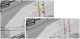
I then chamfered the edges at a rate of 0.0m with 2 segments in order to create the second edge for the cockpit. I then changed the selection from edge to vertex and selected the 4 vertices on the top of the cockpit. I moved the vertices by moving them on the y-axis by using select and moving via a non-uniform scale.
After doing this, I had to create the glass on the helicopter. I changed the selection to polygon, selected the faces that are going to become the windows for the cockpit. I firstly used the inset tool, to inset each polygon by 3.0.
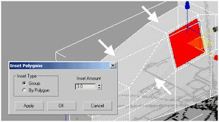
The next step was to use the connect tool on the edges of the cockpit. This was done to give definition to the front area of the cockpit. It was split into 2 segments, with a pinch value of -67 and a slide value of -258.
I then manipulated the front 2 edges in order to make the front of the cockpit match with the blueprints.
The next step was to create the side of the helicopter. Firstly, I selected the edges down the side in order to create a horizontal edge by using the connect tool.
I then selected the vertices and altered them in accordance to the reference image.
The next step was too extrude the side area. I did this by firstly selecting the 4 edges on the side shown below. I also unchecked the Slice Along Mirror parameter as I didn’t want to slice the object in the middle.
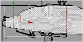
I then selected the polygons shown below, as these are the ones I wanted to extrude.
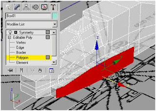
I extruded the faces in accordance with the reference image
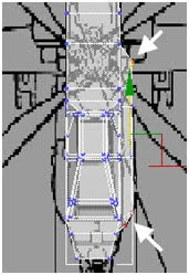
The next step was to make the back wing. This was done selecting 2 faces near the back and simply insetting them.
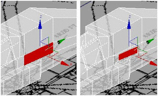
I then extruded the faces and manipulated the vertices in order to fit the blueprints.
The next step was to create the tail. I selected all the edges surrounding the tail and chamfered them in order to portray a smoother profile.
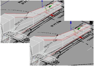
I then selected the faces on the top of the tail and used the inset tool to inset them.
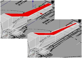
I then changed my selection to Edge and changed the constraints value to Face in order for the edge to move down the face of the polygon and won’t alter the shape of the polygon.
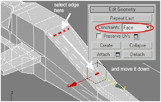
I then extruded the upper part of the tail upwards.
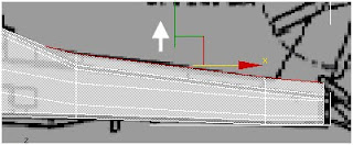
To create the tail, I selected last polygon on the tail part and extruded it, as well as altering the tail part at the top to look like a tail.
To add the rear wings, I cloned the front ring I made earlier and placed it at the back. I then manipulated the vertices in order for it to match the blueprints.
This is what has been produced so far:
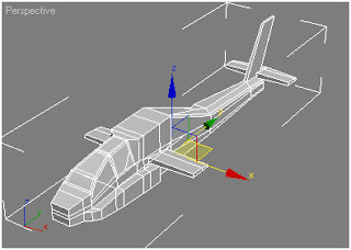
The next step in producing the model was to create the engines on the side of the helicopter. This was done by firstly selecting the edges on the right hand side of the helicopter just behind the wings and using the connect tool to create and extra edge. I then matched up the side of the helicopter with the blueprints.
I then zoomed in on the area where I selected 2 vertexes and used the weld tool. I used a threshold of 100, as this would merge the 2 vertexes together.
I then selected two polygons on the side and extruded it slightly. I then changed the selection to vertex and changed the uppermost vertexes and brought them down.
I then dragged the selected face out, whilst using the blueprint to match it up completely.
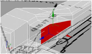
I then selected the face that is slanted and selected hinge from edge in order to make it match up with the blueprint.
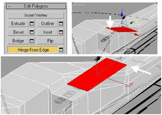
I then selected the 2 edges on the top and bottom of the extruded area and chamfered them.
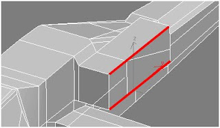
I then moved to the back of the box. I used the connect tool to create new vertical edges seen below. I then used the target weld tool to weld the vertices together.
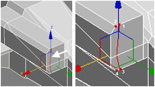
I then selected the three vertices I made and moved them according to the blueprints.
The next step was to manipulate the front of the box. I firstly selected the front area of the box and extruded it, insetted it and bevelled it to obtain the following effect.
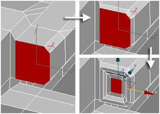
The next step was to weld the vertices in the corners and then whilst using the select and non-uniform scale tool, alter the polygon to make it smaller.
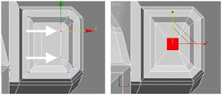
The next step was to extrude the polygon. I then selected the edges surrounding the newly extruded polygon and used the connect tool to create 3 new edges.
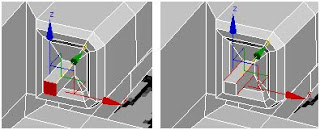
I then altered the vertices to match up with the top blueprint in order to create the following.
The next step was to finish the front of the helicopter off. I firstly selected the top part of the nose and bevelled it twice. I then bevelled the bottom part of the nose and extruded it to achieve the following.
To finish it off I created a cylinder and attached it to the front of the helicopter. Doing this will allow me to resize the helicopter as one object instead of two separate ones.
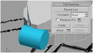
The next step was to create the rotors. I firstly selected all the polygons on the roof of the helicopter and used bevel to create the following.
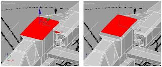
I then selected the polygon in the middle and insetted the polygon to create a square within the selected polygon. I then used chamfer on the inner square to create the following result.
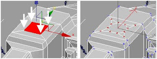
The next step was to create the main rotor blades. I started by making a cylinder and placing it in the new hole I made in the roof.
I then used a combination of inset, extrude and bevel to create the shape below.
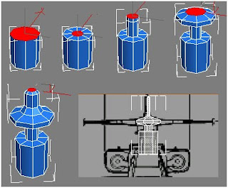
I then selected four polygons; each one needs to be one polygon apart. I then extruded the selected polygons in order to make the main rotor.
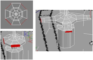
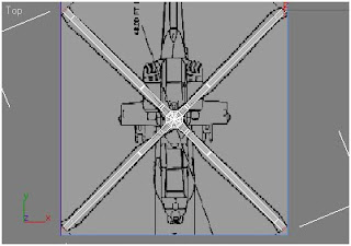
I then manipulated the vertices in order for the rotors to match up with the top blueprint
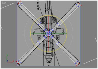
The next part was to create the tail rotor. Firstly I simply cloned the main rotor as a new object.
I then rotated the copied blades 90 degrees, using the angle snap toggle in order to ease the rotation.
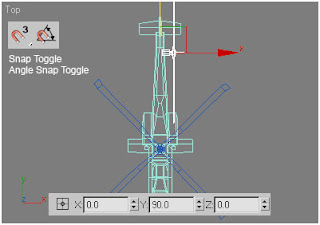
I the selected all the polygons near the start of the rotor, shown in the picture below. I deleted them and selected the edges shown below and used the cap option.
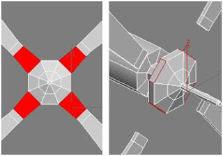
I used the cap option with the polygons at the end of the rotor as well.
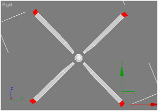
The next step was to connect the blades together. This was done by selecting the edges of the opposing blades and using the bridge option to connect them together.
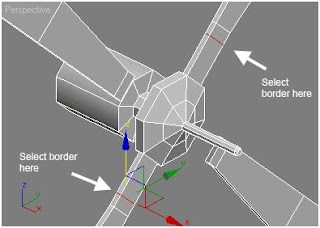
The next step was to move the blades so one is in front of the other.
I then altered the size of the blades in order to suit the blueprints.
The next step was to model the accessories like the machine guns and rockets. Firstly, I modelled a cylinder and insetted one end of it to create the following.
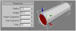
I then selected the two top edges and used the connect tool to create 2 extra edges on the top. I then used slide to move the 2 new edges back and then used bevel and extrude to make a holder for the machine gun.
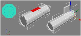
I used the clone tool to create them on other side.
The next step was to make the missiles. I created a long cylinder and moved the vertexes in the middle towards the back. I then bevelled the polygons at the back to create the back end of the missile.
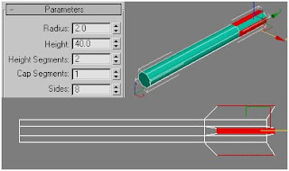
At the top, I bevelled twice to create to more segments as well as making the missile pointed. I then selected the four faces on the front of the missile and bevelled them. I then cloned the missiles 3 times.
The next step was to create a missile grip. This was done by simply extruding a box and then placing the missiles in accordance to the box.
I then positioned the machine gun and the missiles in the correct positions on the helicopter.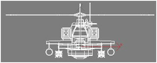
The next step was applying materials to it. I firstly set IDs over the helicopter, the main body was ID 1, the window was ID 2, ID 3 was the missile, rotor housing and machine gun colour and ID 4 was the extra missile colour.
After applying the textures, this is the finished outcome.


No comments:
Post a Comment