Creating a Rubics Cube
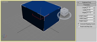
This is a step-by-step record of the development of a rubics cube. Firstly, we need to develop a cube. This is done by using the standard primitives box on the right hand side of the screen and selecting the box tool. You then click and drag to develop a simple square shape, followed by an up or down drag to create the cube. If you are not happy with the dimensions, you can edit them in the parameters window.

I will change the parameters to be 100 x 100 x 100, in order to create a cube.

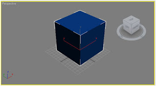
As a rubics cube has 9 squares on each face, we need to segment the cube, by changing the length seg, width seg and height seg values from 1 to 3.
This is a step-by-step record of the development of a rubics cube. Firstly, we need to develop a cube. This is done by using the standard primitives box on the right hand side of the screen and selecting the box tool. You then click and drag to develop a simple square shape, followed by an up or down drag to create the cube. If you are not happy with the dimensions, you can edit them in the parameters window.

I will change the parameters to be 100 x 100 x 100, in order to create a cube.

As a rubics cube has 9 squares on each face, we need to segment the cube, by changing the length seg, width seg and height seg values from 1 to 3.
In order to edit the cube in order to make it look like a rubics cube, it will need to be converted in to an editable poly. This is done by simply right-clicking the word “box” in the modifier menu and clicking “convert to: editable poly.”
After this is done, we need to select the all the polygons and bevel them in order to create the single squares you can see on a rubics cube. This can be done by selecting the bevel button in the “edit polygons” category in the modify menu. If you select the box next to the button, a menu will pop up.
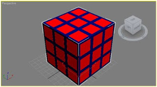
In this menu box, change the bevel type from group to by polygon, change the height from 10.0 to 0.0 and then change the outline amount from -1.0 to -2.0. Doing this will create the following cube:

To make the squares extrude, we can re-edit the bevel input again by changing the height from 0.0 to 5.0 and the outline amount from -2.0 to 0.0. Doing this will create the following cube:


